안전분석 엔지니어링 서비스
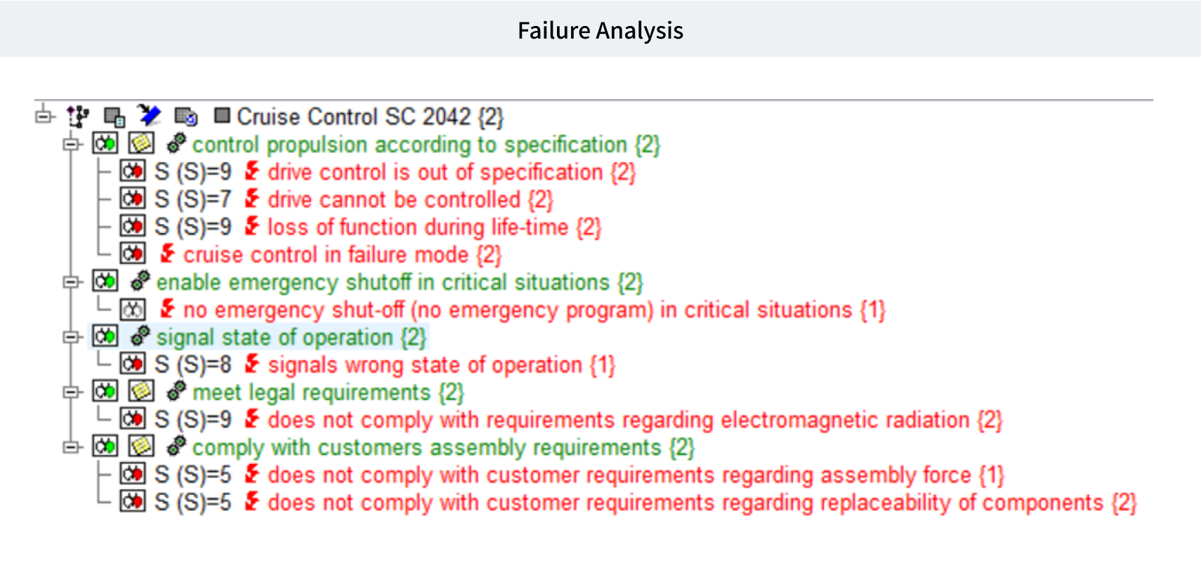
FMEA (Failure Mode and effects analysis)
Concept
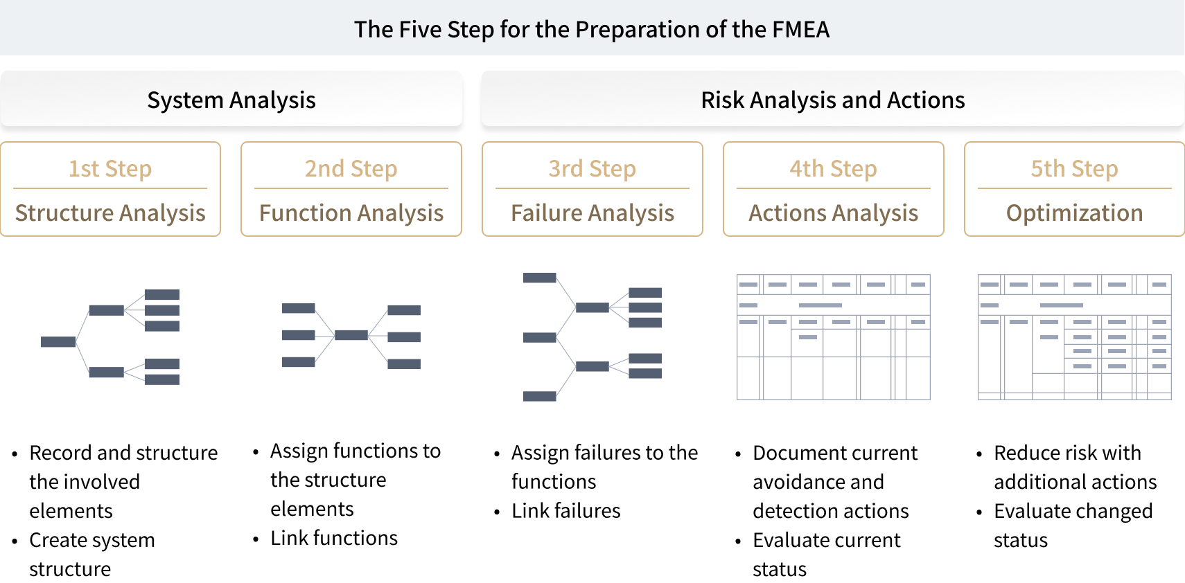
FMEA는 시스템이나 하드웨어, 소프트웨어의 기능이나 설계/프로세스 상에서 발생할 수 있는 고장 모드(Failure Modes)의 위험도를 평가하고, 원인(Causes)과 영향(Impact)을 분석하여, 고장 모드의 발생 가능성을 낮추거나 회피하는 방안을 정의하기 위해 사용되는 경험에 의한 안전분석 방법이다. FMEA는 전형적인 귀납적 분석방법이며, ‘Bottom-up’방식으로 진행된다. 또한 고장 모드의 중요성에 따라 정성적이나 정량적으로 분석이 가능하나 주로 정성분석 위주로 사용된다
Service List
- System FMEA
- Hardware FMEA
- Software FMEA
- Process FMEA
Application Domain
- Automotive
- Automation
- Military
- Train
- Avionics
- Medical
- Mobile
- Shipbuilding
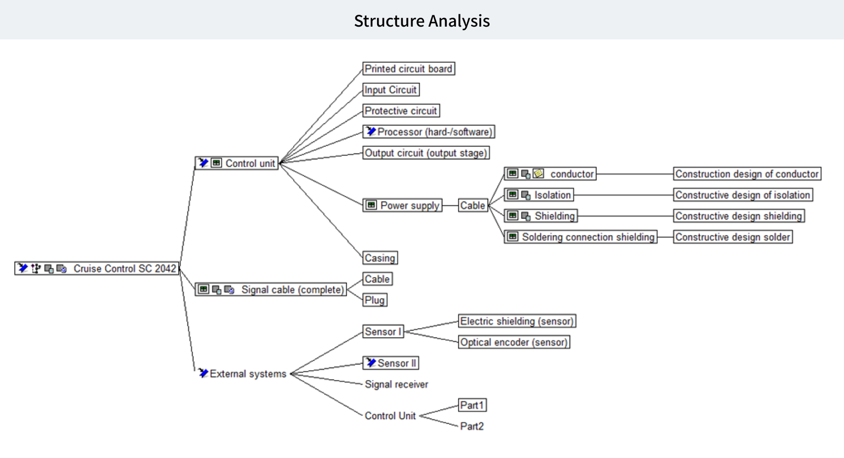
Related Diagram
FTA (Fault Tree Analysis)
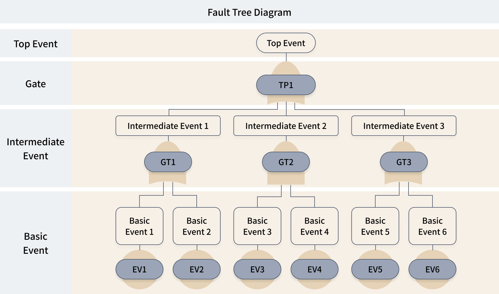
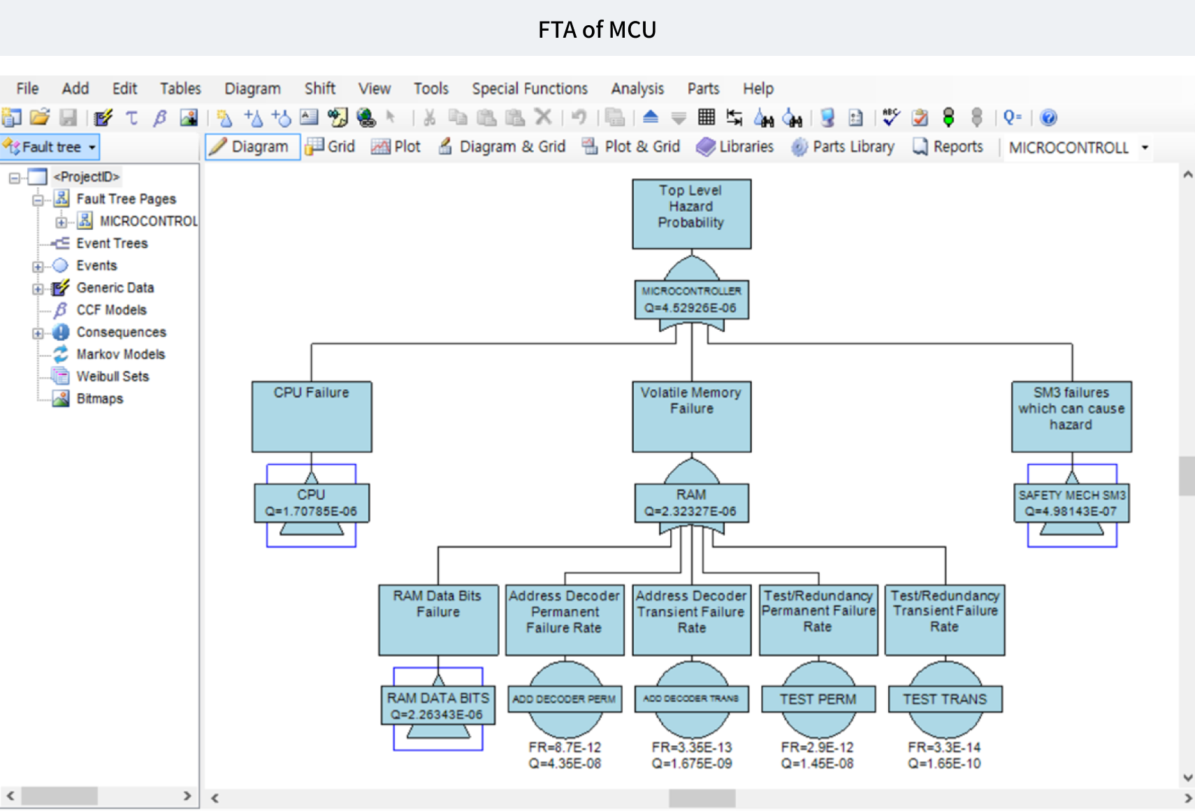
Concept
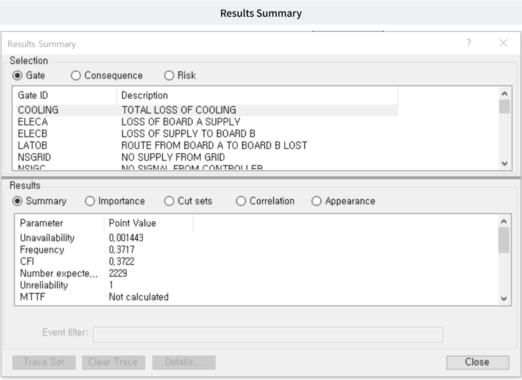
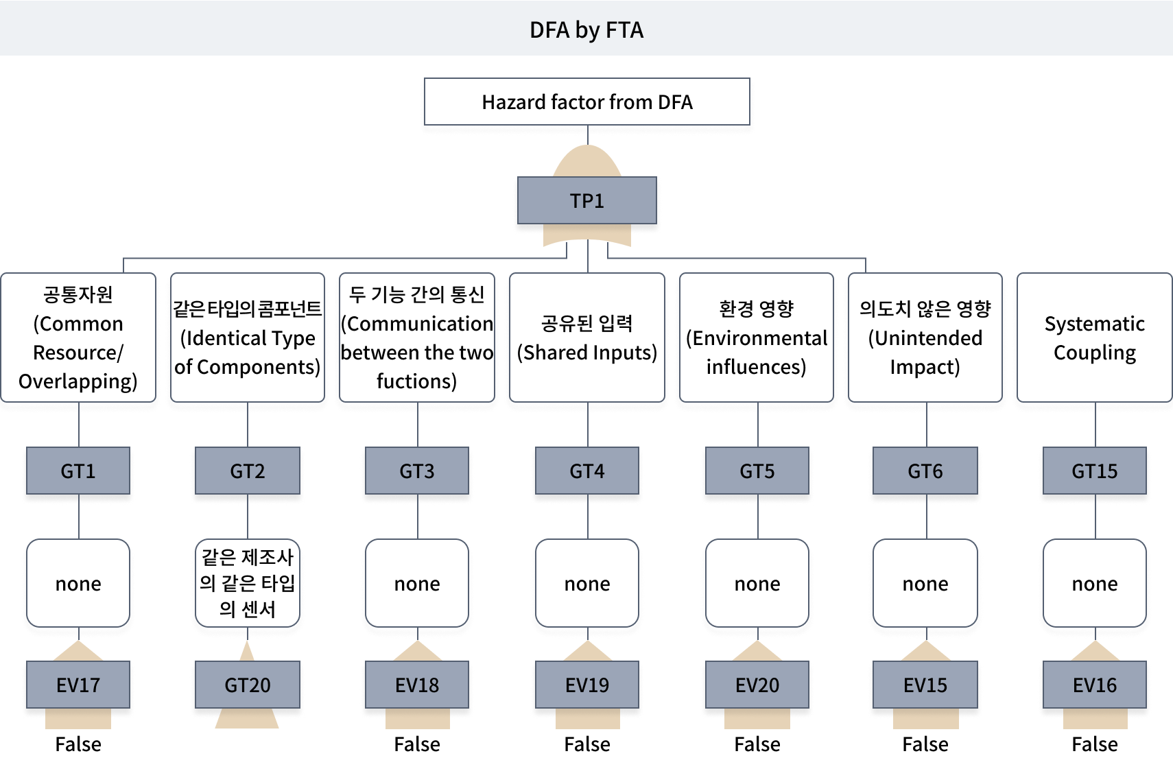
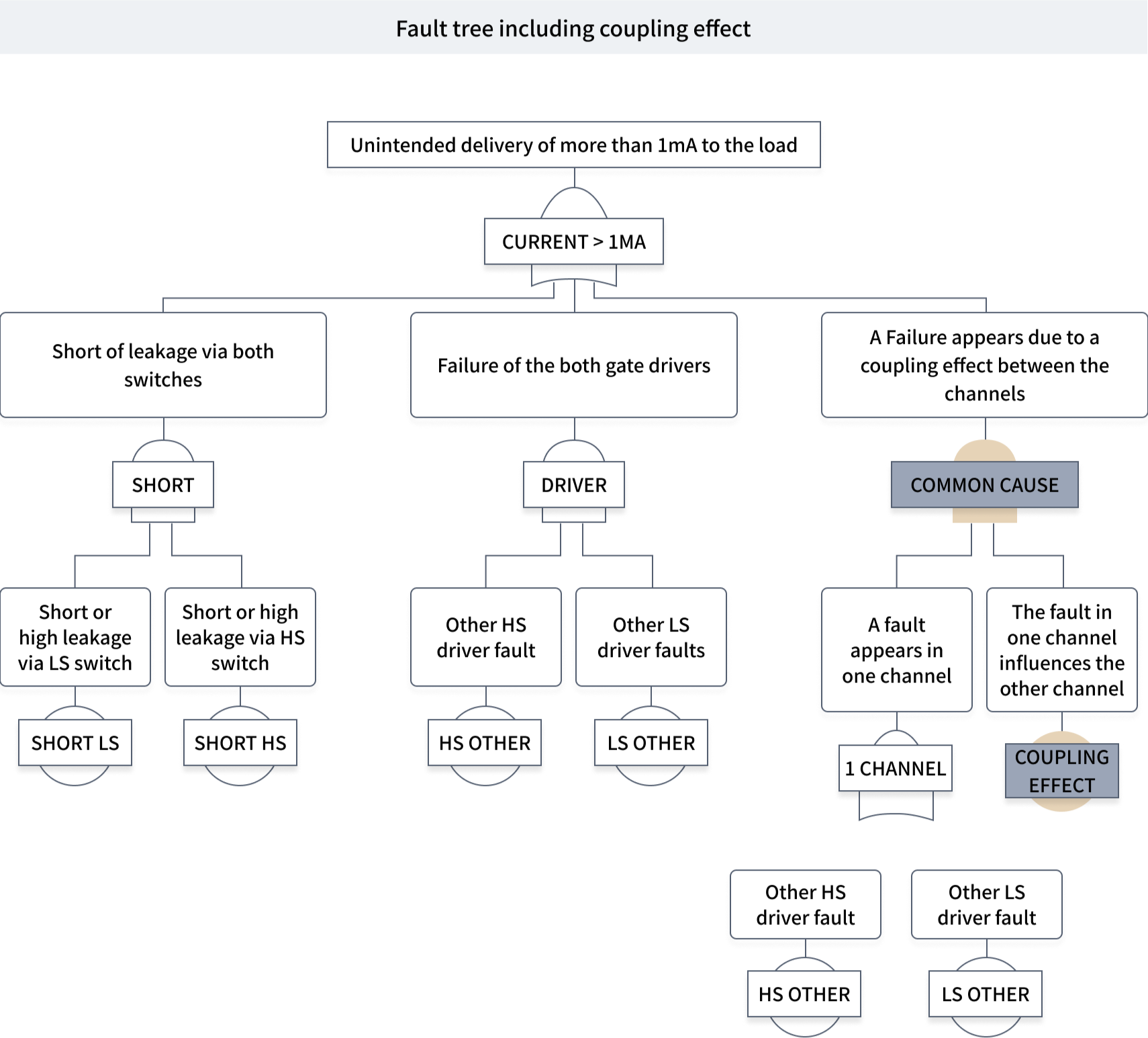
FTA는 정량적 분석이나 정성적 분석에 모두 사용될 수 있는 분석 기법으로써 고장이나 재난 요인(Hazard)의 제거 가능성을 과학적으로 제안할 수 있는 방법이며, 다중 고장으로 인해 발생할 수 있는 복잡한 영향을 분석할 수 있다는 장점이 있다. FTA는 개념은 트리 형식으로 고장 원인을 분석하는 것이다. 차량 상에서 운전자가 인지할 수 있는 최상위 고장(재난 요인: Hazard)을 최상위 고장 이벤트(Undesired Event: UE)로 정의하고, 그 고장 이벤트가 발생할 수 있는 원인을 근본 원인이 파악될 때까지 분석한다. 또한 FTA는 분석 결과에 대해 발생할 수 있는 확률을 계산하면 최상위 고장 이벤트가 발생할 수 있는 확률을 계산할 수 있다. FTA는 각각의 근본 원인이 발생할 수 있는 확률을 줄여주기 위한 솔루션 이벤트들을 추가하여 고장이 발생할 수 있는 확률을 줄여주는 것이 목표이다.
Service List
- System FTA
- Hardware FTA (qualitative + quantitative)
- Software FTA
- Process FTA
Application Domain
- Automotive
- Automation
- Military
- Train
- Avionics
- Medical
- Mobile
- Shipbuilding
Related Diagram
DFA (Dependent Failure Analysis)
Concept
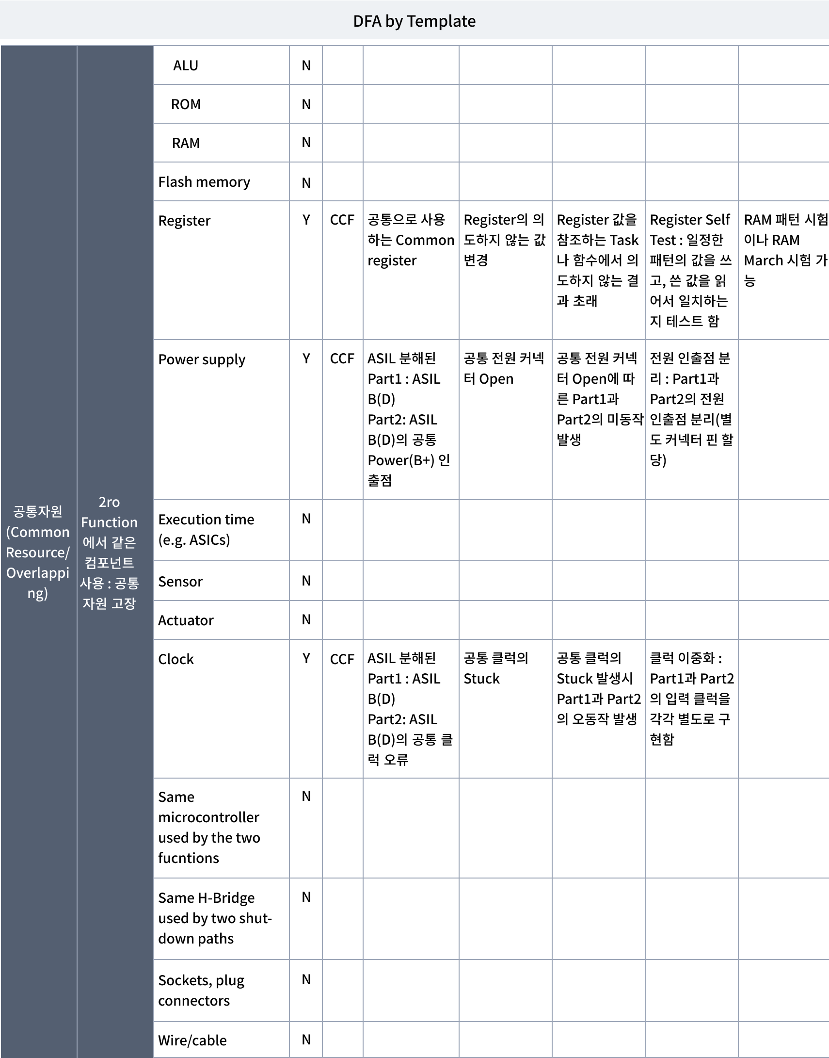
의존 고장은 하나의 컴포넌트의 고장이 다른 고장과 연관되는 경우로, 서로 독립적인 경우와 구별된다. 이러한 경우는 설계상에 하나의 컴포넌트와 다른 컴포넌트가 인과관계를 가지는 경우 또는 같은(identical) 컴포넌트를 공유하는 경우 발생 할 수 있다.
의존고장의 종류
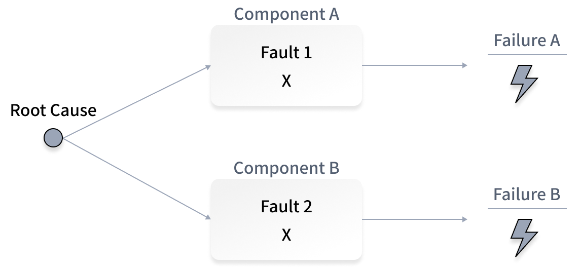
- 공통 원인 고장 (CCF : Common Cause Failure)
하나의 특정 사건이나 근본원인으로 인하여 하나의 아이템에 존재하는 두 개 이상의 엘리먼트를 고장에 이르게 하는 고장이다. 특히 안전관점에서 기능에 대해 이중 또는 다중구조의 형태의 설계 시 필연적으로 나타날 수 있는 문제점이다. 예를 들면, 같은 리소스 또는 입력 값의 사용시 입력으로 사용되는 리소스 또는 값이 문제를 일으킬 시, 연결되어 있는 모든 기능들이 고장을 일으킨다. 공통 원인 고장은 의존 고장의 한 종류이며, 연계 고장(Cascading failure)과 구분된다.
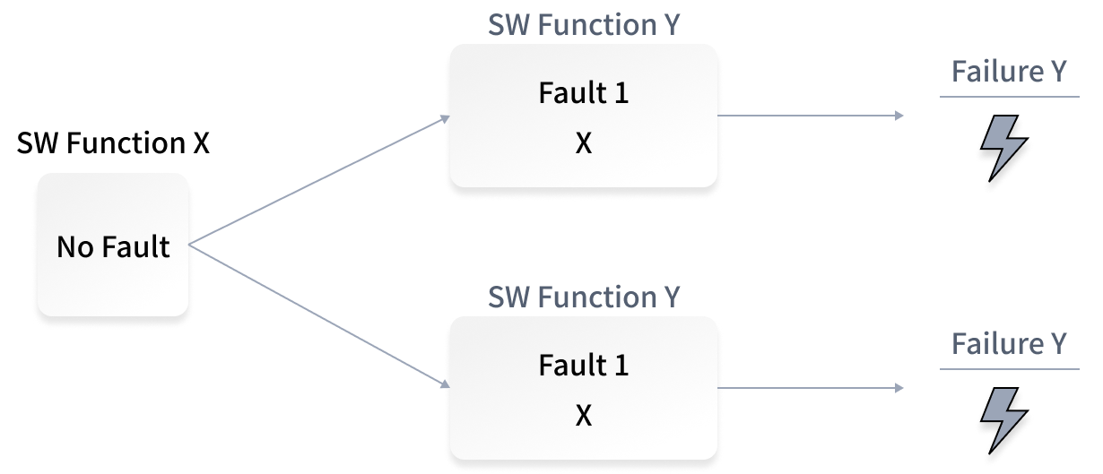
- 공통 모드 고장 (CMF : Common Mode Failure)
공통 모드 고장은 공통 원인 고장의 한 종류로서, 여러 컴포넌트 및 부품이 같은 모드(시간)에서 동시에 고장을 일으키는 현상이다. 예를 들면 아래 그림과 같이 동일한 소프트웨어로 이중구조의 설계에서 동일 소프트웨어에서 문제가 발생시 입력에 관계 없이 고장을 일으키게 된다.
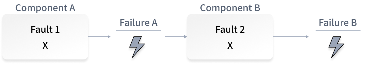
- 연계 고장 (CF : Cascading Failure)
연계 고장은 같은 아이템에 존재하는 엘리먼트나 또 다른 엘리먼트의 고장에 의해서 아이템의 엘리먼트에 발생하는 고장이며, 한 부품 또는 컴포넌트에서 발생한 고장이 한 시스템에 있는 여려 부품 및 컴포넌트 고장을 일으키게 되는 현상이다. 특히 전원 분배와 관련된 계통도에서 한 부하에서 여러 경로로 부하를 전달할 때, 한 경로에 있는 부품이 고장을 일으켜 그 경로를 사용할 수 없게 된다면, 연결되어 있는 남은 경로의 부품들이 고장을 일으킬 수 있다. 연계 고장은 의존 고장의 한 종류이며, 공통 원인 고장(Common cause failure, CCF)과 구분된다.
Service List
- System DFA
- Hardware DFA
- Software DFA
Application Domain
- Automotive
- Automation
- Military
- Train
- Avionics
- Medical
- Mobile
- Shipbuilding
Related Diagram
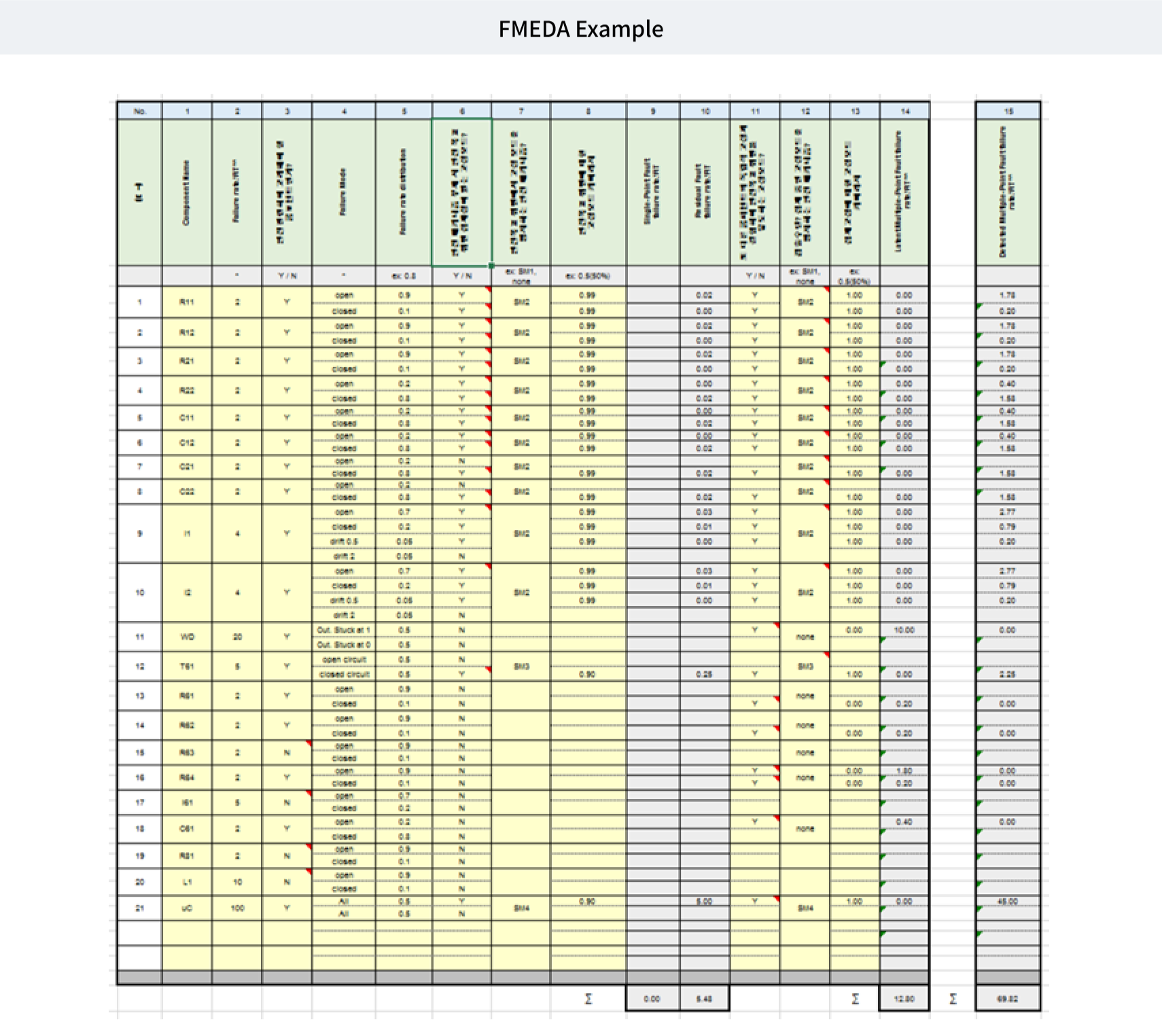
FMEDA (Failure Mode Effect & Diagnosis Analysis)
Concept
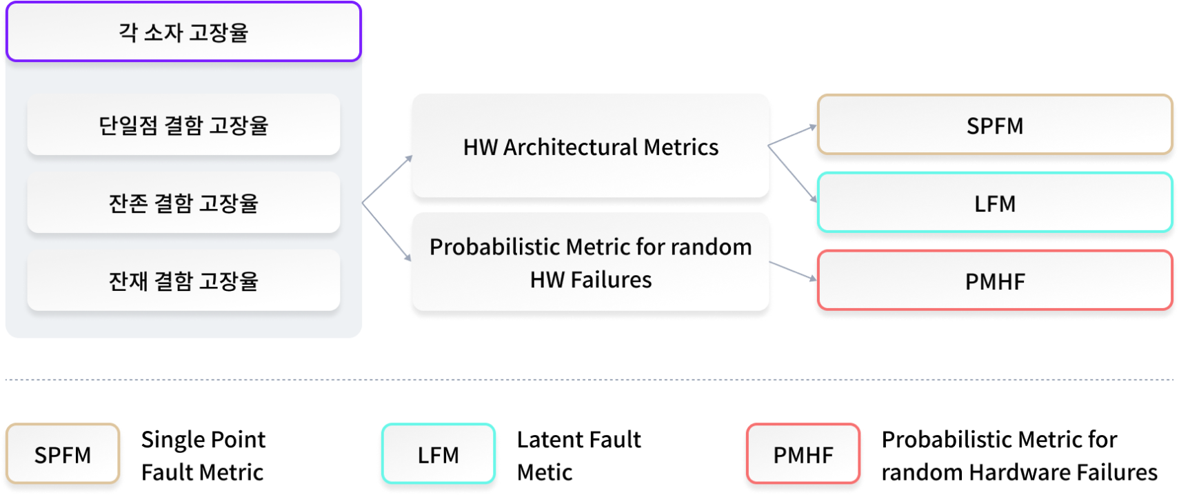
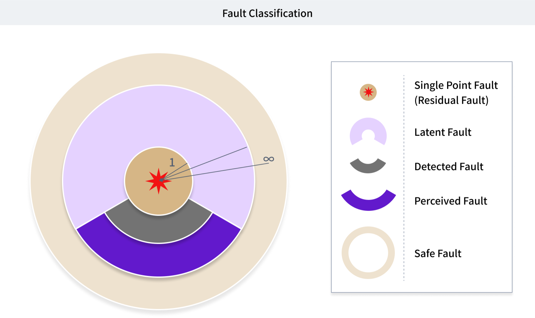
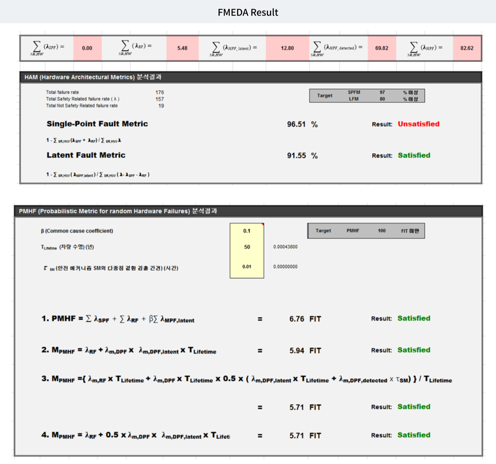
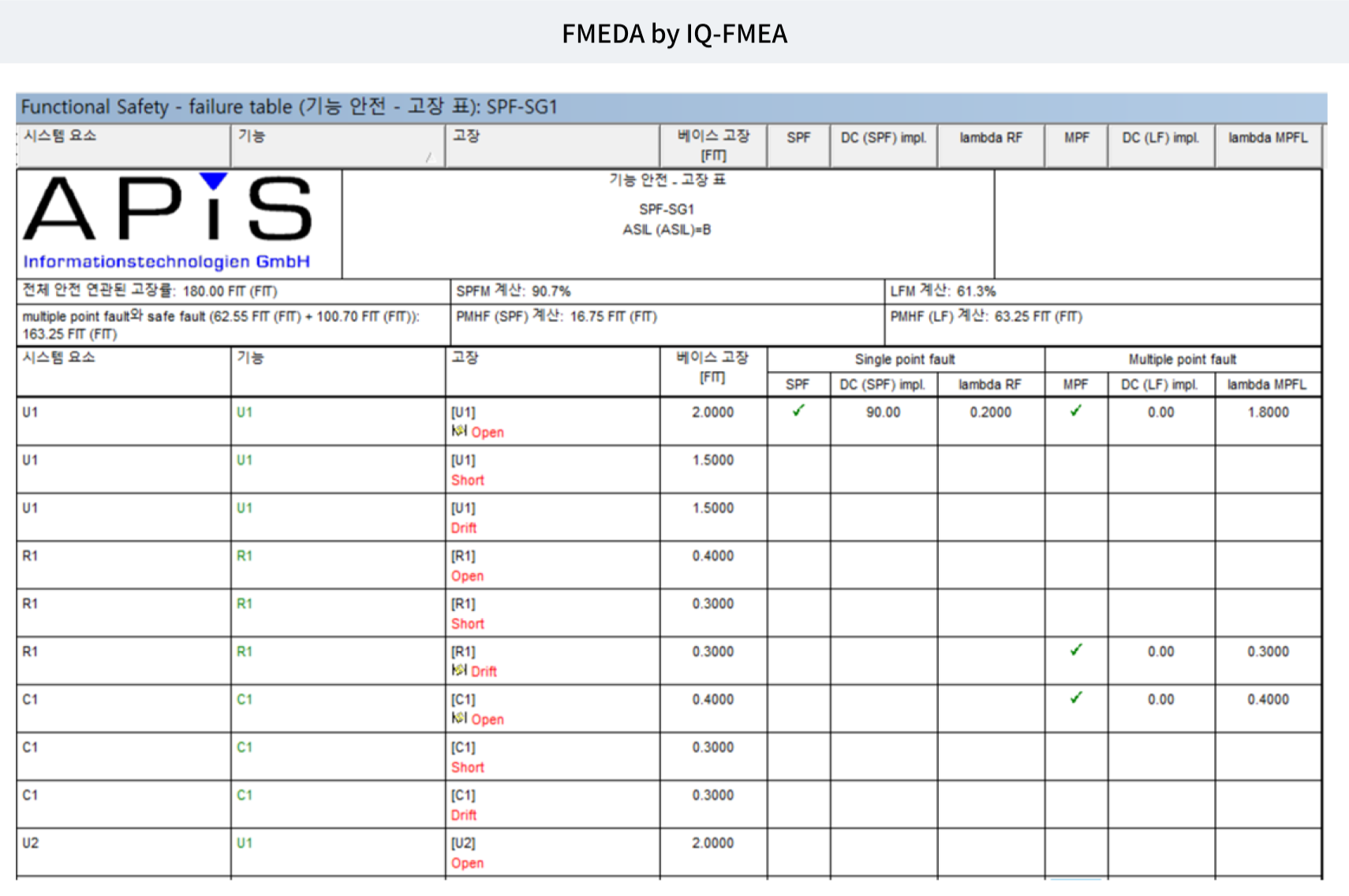
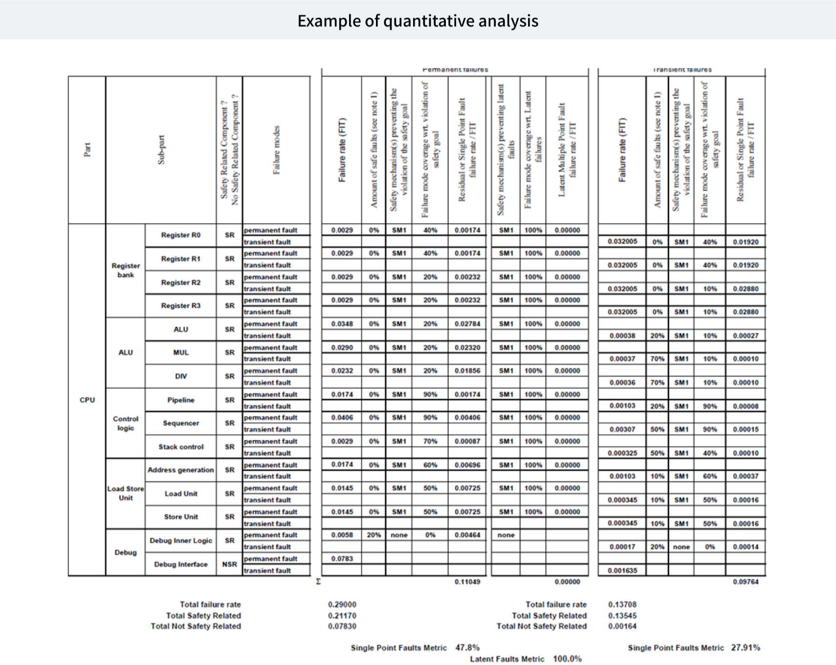
하드웨어 개발과정에서 안전목표 위배 가능성을 제거하기 위하여 하드웨어 각 소자의 고장 유형별 고장율 기반으로 단일점 결함, 잔존 결함, 잠재 결함을 계산하여 HAM(Hardware Architectural Metrics)과 PMHF (Probabilistic evaluation of random hardware failures)를 산출을 통하여 안전 등급(ex. ASIL)에 따른 정량적 목표 값에 대한 충족 여부를 평가한다.
Service List
- Hardware Architectural Metrics (Single Point Fault Metric, Latent Fault Metric)
- PMHF (Probabilistic Metric for random Hardware Failures)
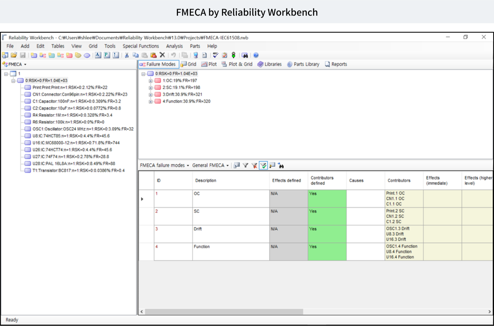
- FMECA (Failure Modes, Effects & Criticality Analysis)
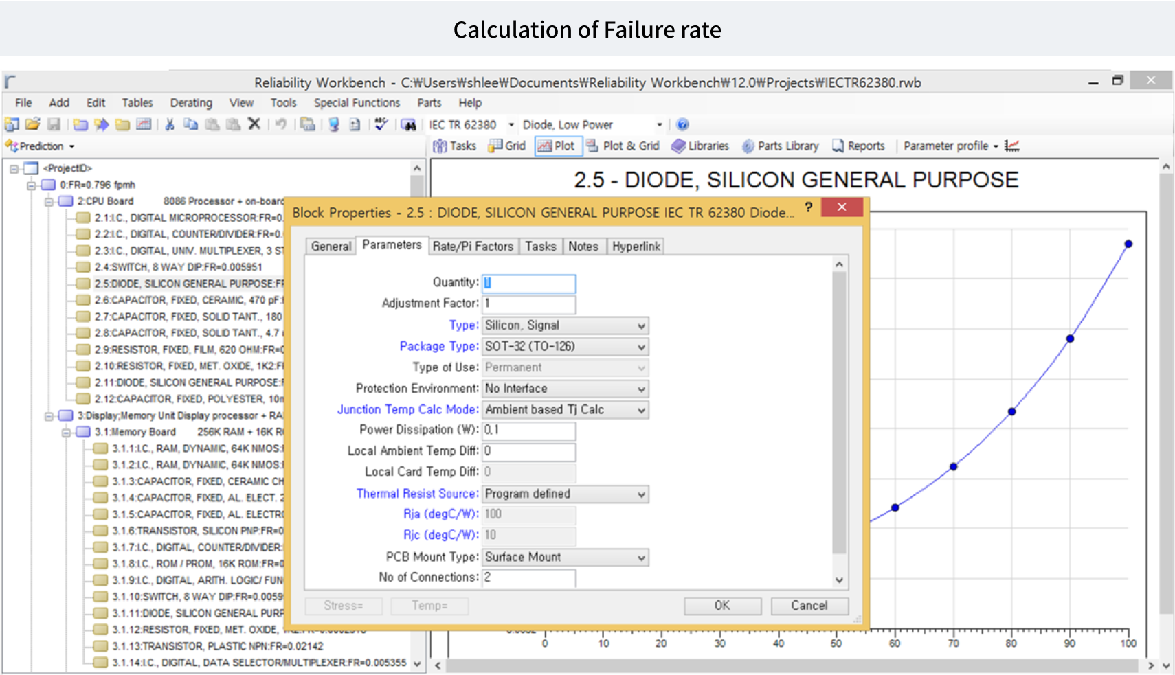
- Various System & Hardware Reliability Analysis
- Hardware component failure rate(FIT) Calculation according to IEC TR 62380, SN29500, Telcordia TR/SR, MIL-217, NSWC, GJB/z, FIDES
- Safety Mechanism Diagnostic Coverage Calculation
Application Domain
- Automotive
- Automation
- Military
- Train
- Avionics
- Medical
- Mobile
- Shipbuilding
Related Diagram
Semiconductor Safety Analysis
Concept
반도체 부품 레벨의 안전 요구사항 만족 여부 평가를 위한 안전분석 활동임.(ISO PAS 19451 적용, ISO 26262 2'nd edition part11적용)
Semiconductor FMEA
- 반도체 내부 구조 분석
- 반도체 내부 블록 기능 정의
- 반도체 내부 블록 오류 정의
- 반도체 내부 Safety Mechanism 정의
- 반도체 FMEA 산출
- 반도체 안전 요구사항 도출
Semiconductor FMEDA
- 반도체 내부 구조 분석
- 반도체 내부 블록 기능 정의
- 반도체 내부 블록 오류 정의
- 반도체 내부 Safety Mechanism 정의
- 반도체 FMEA 산출
- 반도체 안전 요구사항 도출
Semiconductor FTA
- 반도체 내부 Failure 분석
- 정성적 FTA 분석
- Minimal Cutset 실시
- 정량적 FTA 분석
- Failure Frequency (ω), C.F.I (𝛌) 산출
Semiconductor DFA
- 반도체 내부 Independency확인
- Redundant element 분석
- Dependent failures initiators 분석
- Measure for fault avoidance or control 분석
- Verification method 분석
Service List
- Semiconductor FMEA
- Semiconductor FMEDA
- Semiconductor FTA
- Semiconductor DFA
Application Domain
- Digital components
- Analog components
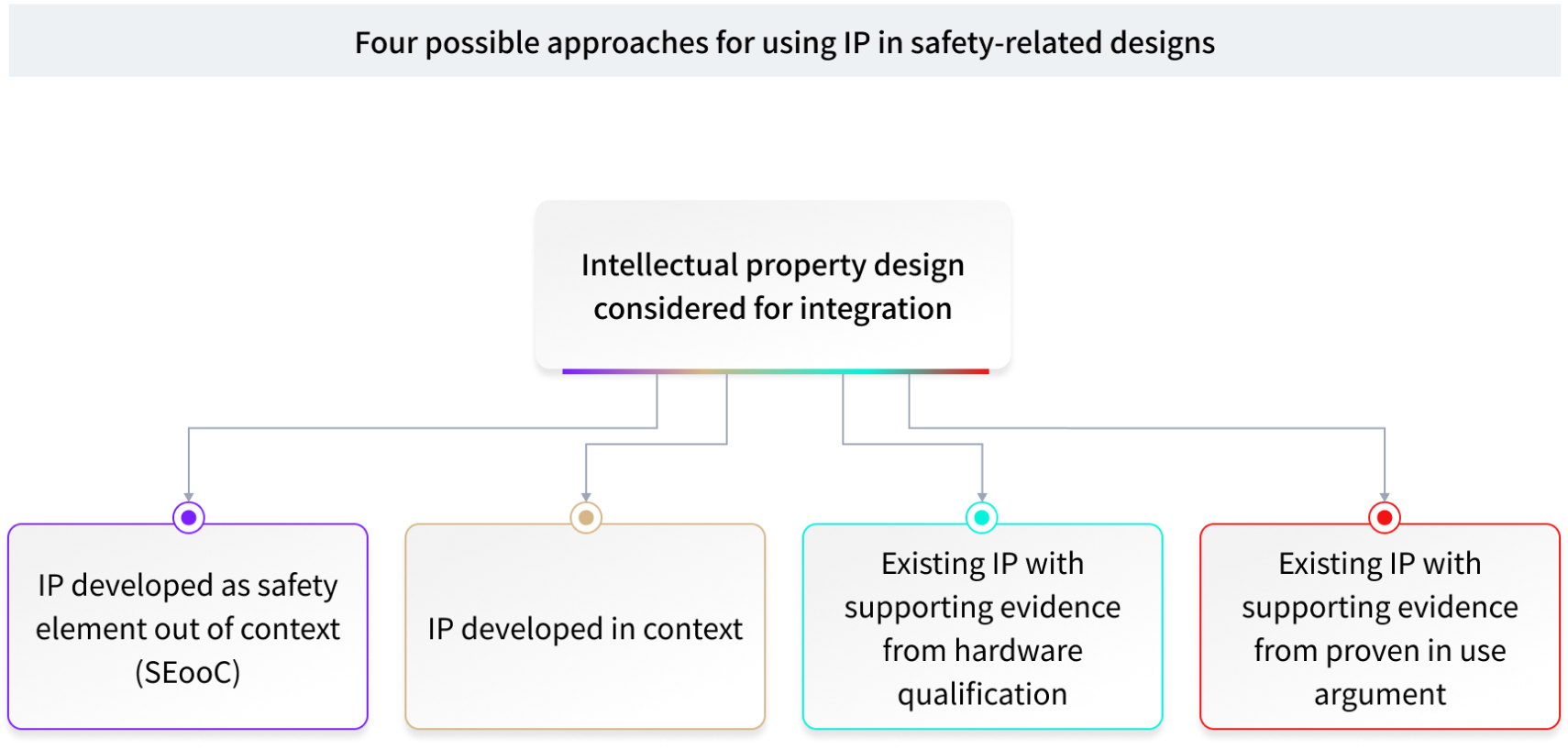
- Intellectual Property
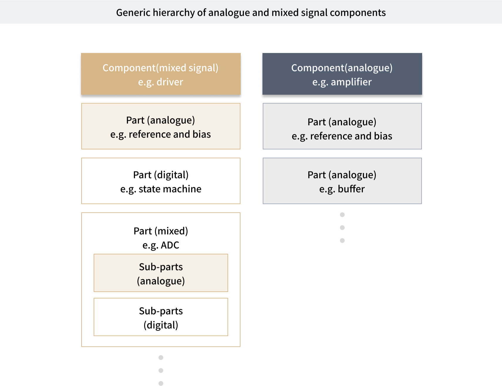
- Mixed signal components
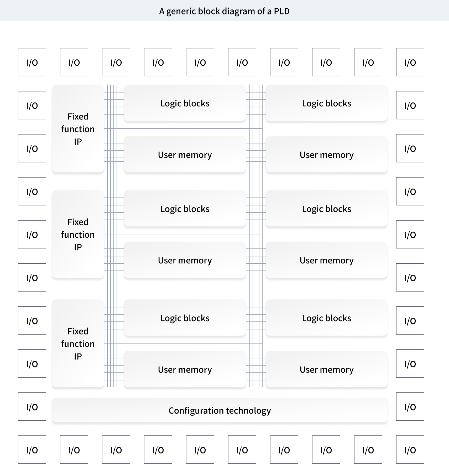
- Programmable logic devices
- Microcontroller
- Multi-core components
- Sensors
- Transducers
Related Diagram
Software Product Line Engineering
Software Product Line Engineering(SPLE)에 대하여
소프트웨어 제품라인 공학은 재사용의 기술과 함께 비즈니스 이익과 기술적인 전략을 함께 고려하는 소프트웨어 개발 패러다임입니다. 소프트웨어의 개발 시간은 줄이고 동시에 품질경쟁력을 확보하는 문제를 해결하기 위해 국내외적으로 가장 주목 받고 있는 기술입니다. 소프트웨어 제품라인(Software Product Line)은 공통된 휘처들이 공유하는 소프트웨어 집약적 시스템들의 집합을 의미하며, 이 시스템들은 목표시장의 특유의 요구사항을 만족시키는 공통된 핵심 자산을 이용하여 개발되어집니다.
소프트웨어 제품라인 공학(Software Product Line Engineering)은 공통된 핵심 자산을 만들고 자산을 제품 생산에 이용하여 관련된 일련의 제품을 만드는 방법론, 기술, 지원환경을 제공합니다.
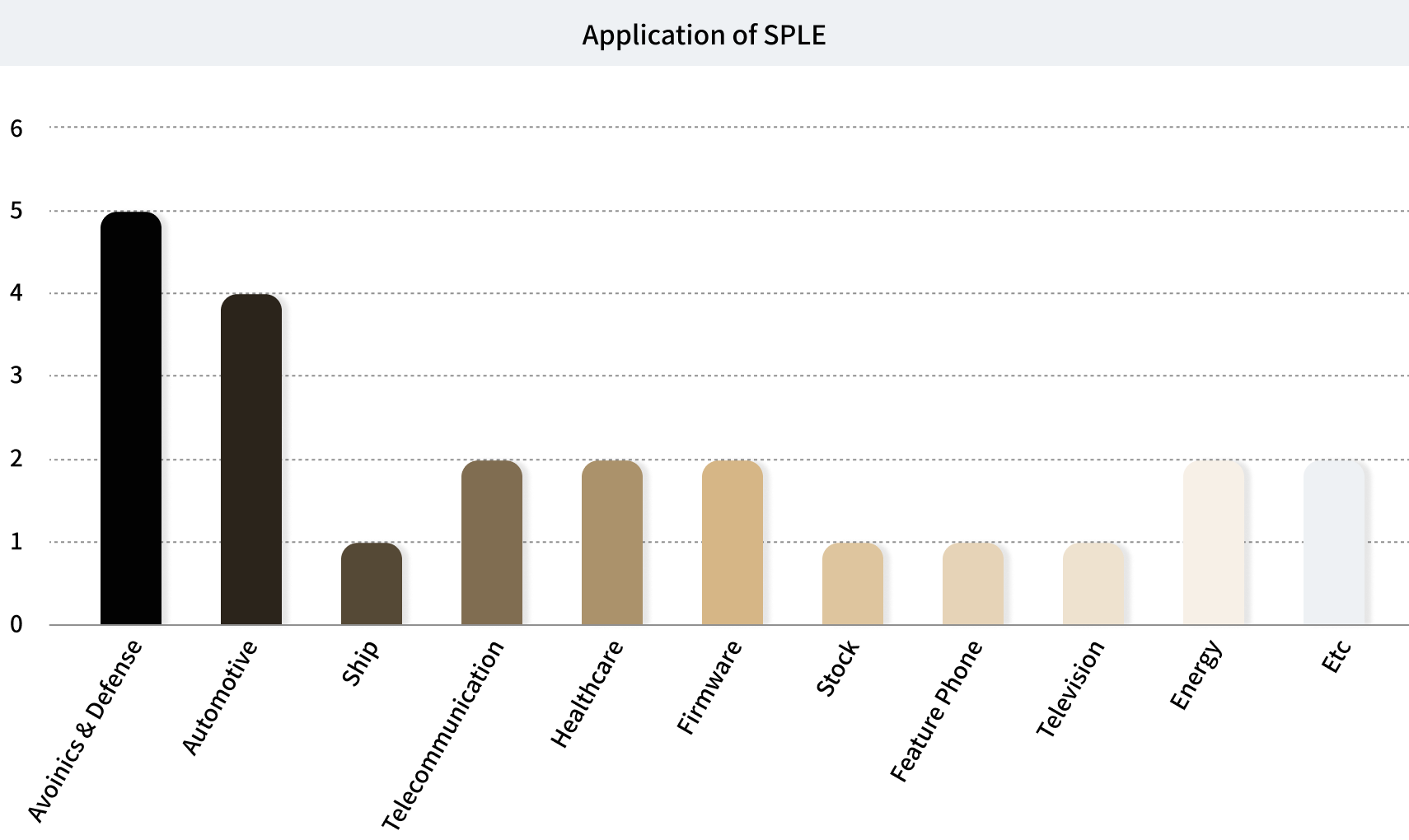
SPLC(Software Product Line Conference)가 관리하는 소프트웨어 제품라인 성공사례(Hall of Fame)의 자료를 살펴보면 자동차, 항공, 그리고 국방 도메인을 중심으로 제품라인공학을 도입한 성공사례를 발표하고 있습니다. (☞ Hall of Fame – SPLC.net, http://splc.net/fame.html) 특히, 자동차 도메인의 개발모델인 AUTOSAR나 개발언어인 EAST-ADL등에서 제품라인 기술을 공식적으로 적용하고 있습니다.(☞ EAST-ADL Association, http://www.east-adl.info)
SPLE Service
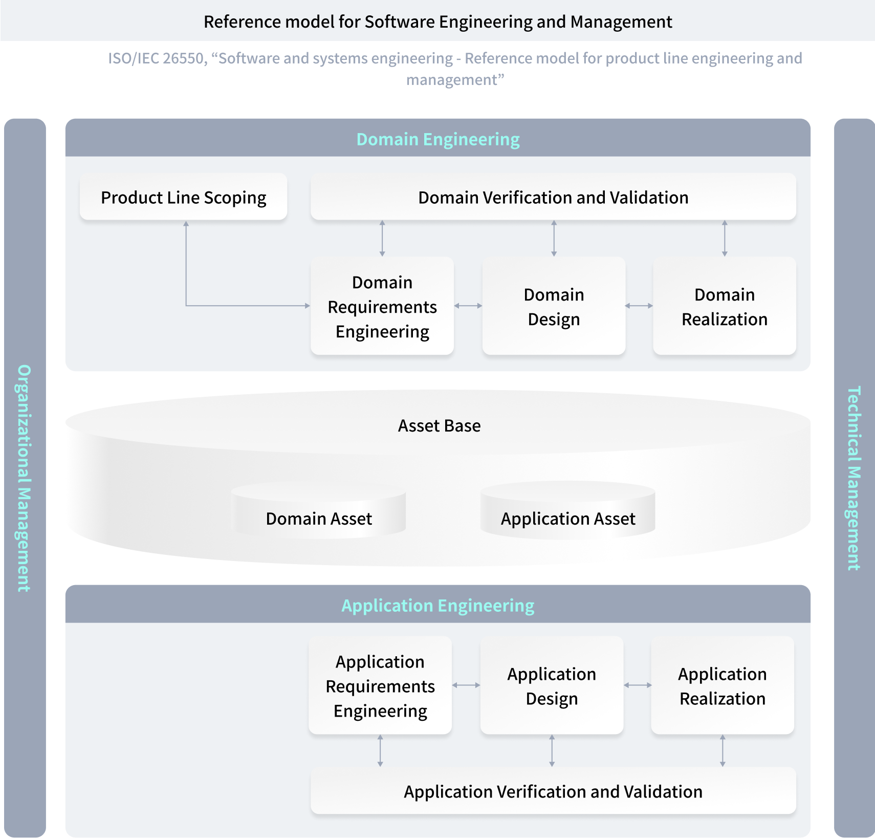
SPLE는 일반적인 소프트웨어 개발과는 달리 자산을 개발하는 도메인 엔지니어링과 개발된 자산을 제품으로 구성하는 어플리케이션 엔지니어링 단계로 구분됩니다.
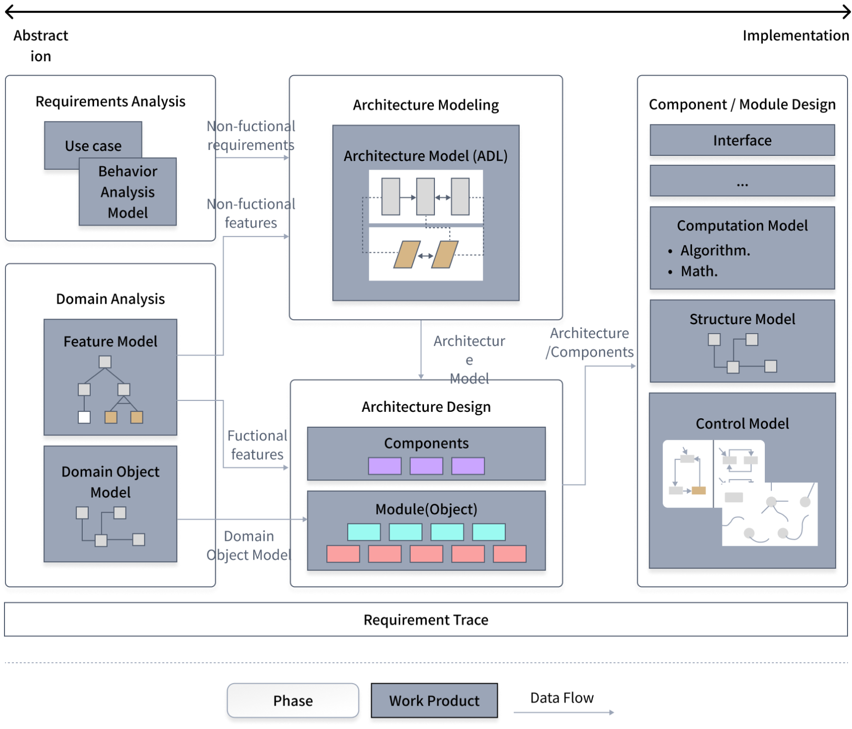
SPID는 소프트웨어 도메인을 분석하고 자산을 개발하는 도메인 엔지니어링과 효율적이고 효과적인 제품 생성을 위해 FORM(Feature-Oriented Reuse Method)[4] 기반의 다양한 엔지니어링 서비스를 제공합니다.
- 도메인 분석 및 모델링
- 제품라인 요구사항 분석 및 명세 방법
- 제품라인 아키텍처 설계방법
- 제품라인 컴포넌트/모듈 설계방법
- 제품라인 구현 기술 적용
Related Standard & Resources
- Feature Model (de facto standard)
- ISO/IEC 26550 Software and System Engineering – Reference model for product line engineering and management
- ISO/IEC 26551 ~ ISO/IEC 26556
- 지원 도구 : ☞ VULCAN Workbench
SW 분석 및 설계 지원
고 품질의 제품을 적기에 Delivery하기 위해 SW Engineering 원리에 기반한 분석/설계/구현/테스트 수행 컨설팅을 제공합니다. 또한 조직의 SW Engineering 역량 수준을 제고할 수 있도록 표준화되고 최적화 된 SW 개발 프로세스를 제공합니다.
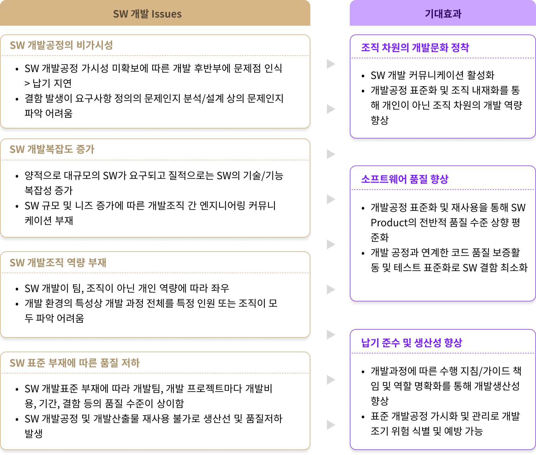
SW 개발에 따른 주요 이슈
요구사항 정의부터 분석/설계, 구현, 테스트에 이르는 개발과정을 조직 특성에 따라 최적화해 효율적인 SW개발 수행을 지원해 주는 기술, 기법 등의 인프라를 제공합니다.
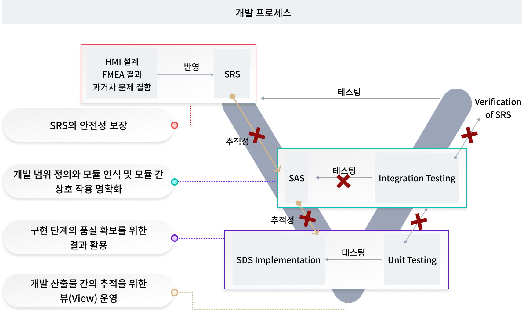
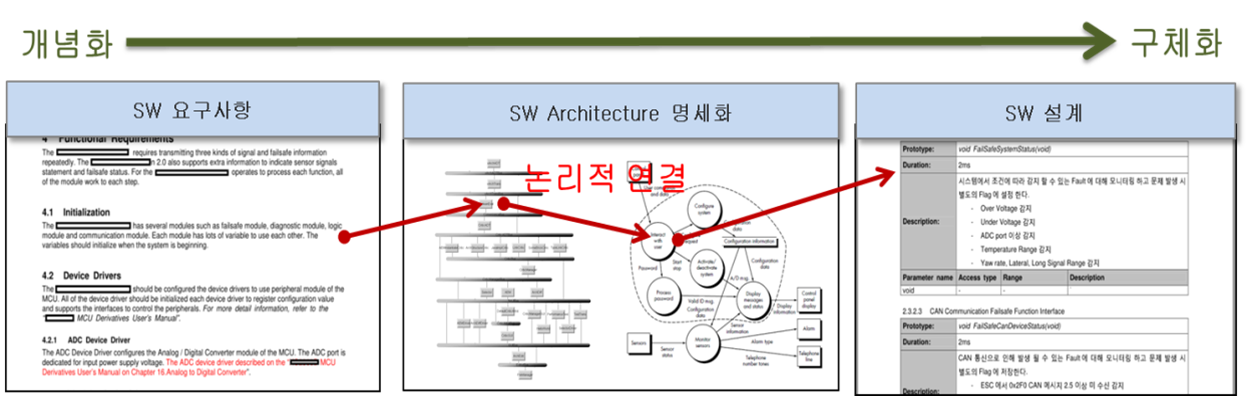
SW 개발프로세스 별 가이드 주요 내용(사례)
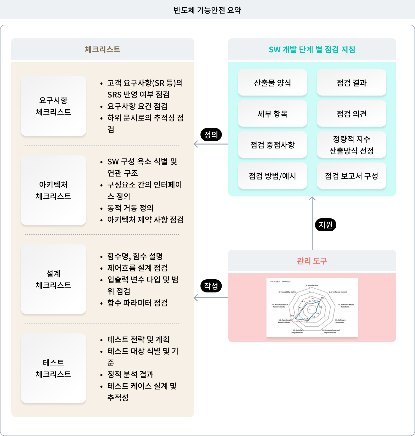
SW 개발프로세스 별 주요 점검 기준(사례)
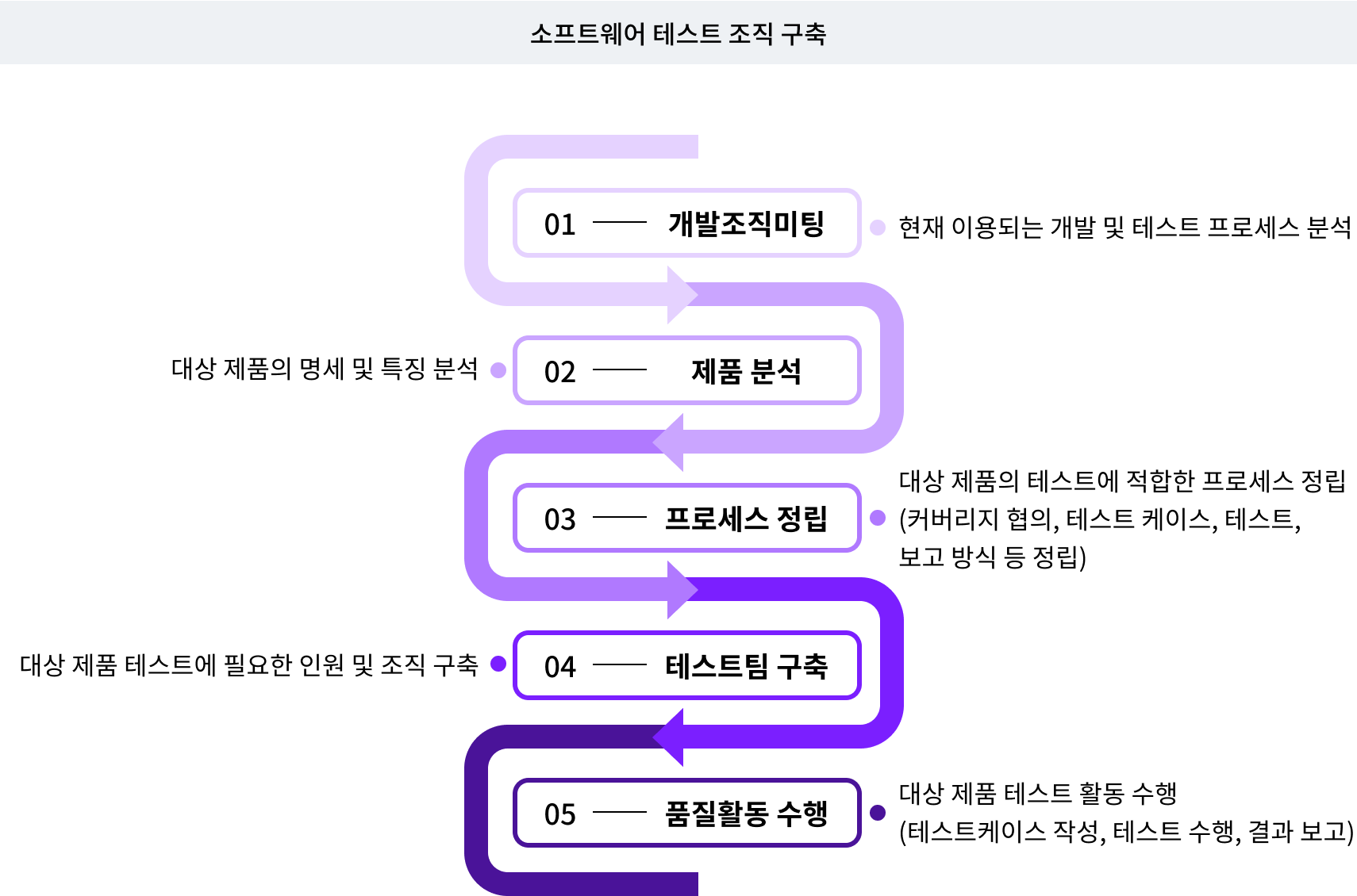
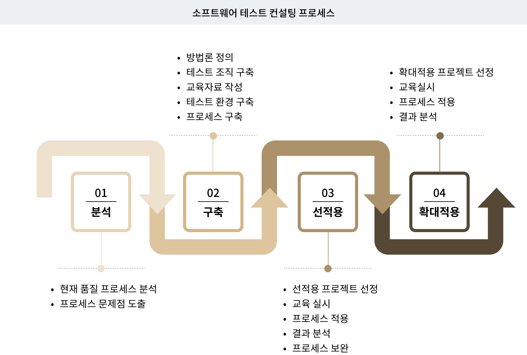
소프트웨어 테스트
다년간의 SW 프로세스 개선 경험을 바탕으로 고객사의 실정에 맞는 맞춤형 Consulting을 제공합니다.
소프트웨어 테스트 개요
요구사항 정의부터 분석/설계, 구현, 테스트에 이르는 개발과정을 조직 특성에 따라 최적화해 효율적인 SW개발 수행을 지원해 주는 기술, 기법 등의 인프라를 제공합니다.
철저한 사전테스트가 필요한 이유
출시될 제품의 결함을 사전에 발견하여 출시 후 발생할 수 있는 SW 재 수정, 재 배포 등에 소요되는 막대한 금전적 손실을 예방하고 회사 이미지 실추를 방지함으로써 제품과 고객의 신뢰를 확보할 수 있습니다.
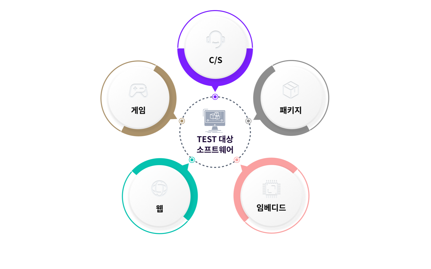
테스트 대상 소프트웨어
웹, 임베디드, C/S, 패키지, 게임 등 SW가 작용되는 다양한 분야의 테스트가 대상입니다.
소프트웨어 테스트 구분
- 기능 테스트
SW의 전체 기능이 구현 의도에 맞게 동작하는지 정상적/비정상적인 동작 시나리오를 이용하여 다양한 실제 상황에서 발생할 수 있는 오류를 발견합니다.
- 성능 테스트
규정된 성능 기준이 있는 경우에는 기준에 부합하는지 테스트하며, 성능 기준이 없는 경우에는 일반적인 기준을 이용하여 성능의 적정성을 테스트합니다.
- 호환성 테스트
SW가 동작되는 HW 환경이 점차 다양해 짐에 따라 여러 종류의 플랫폼에서 정상 동작하는지 확인이 반드시 필요합니다.
- 보안 테스트
권한이 없을 경우 정보에 접근하지 못하는지, 권한이 있을 경우 정보에 접근이 가능한지 다양한 방법으로 테스트 합니다.
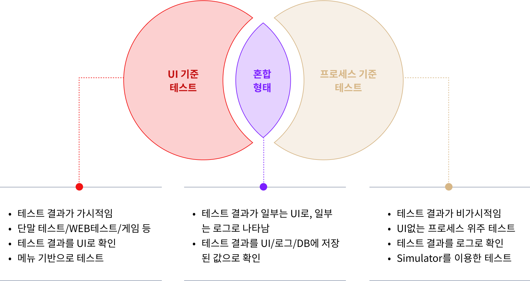
제품의 유형에 따른 테스트
웹, 임베디드, C/S, 패키지, 게임 등 SW가 작용되는 다양한 분야의 테스트가 대상입니다.
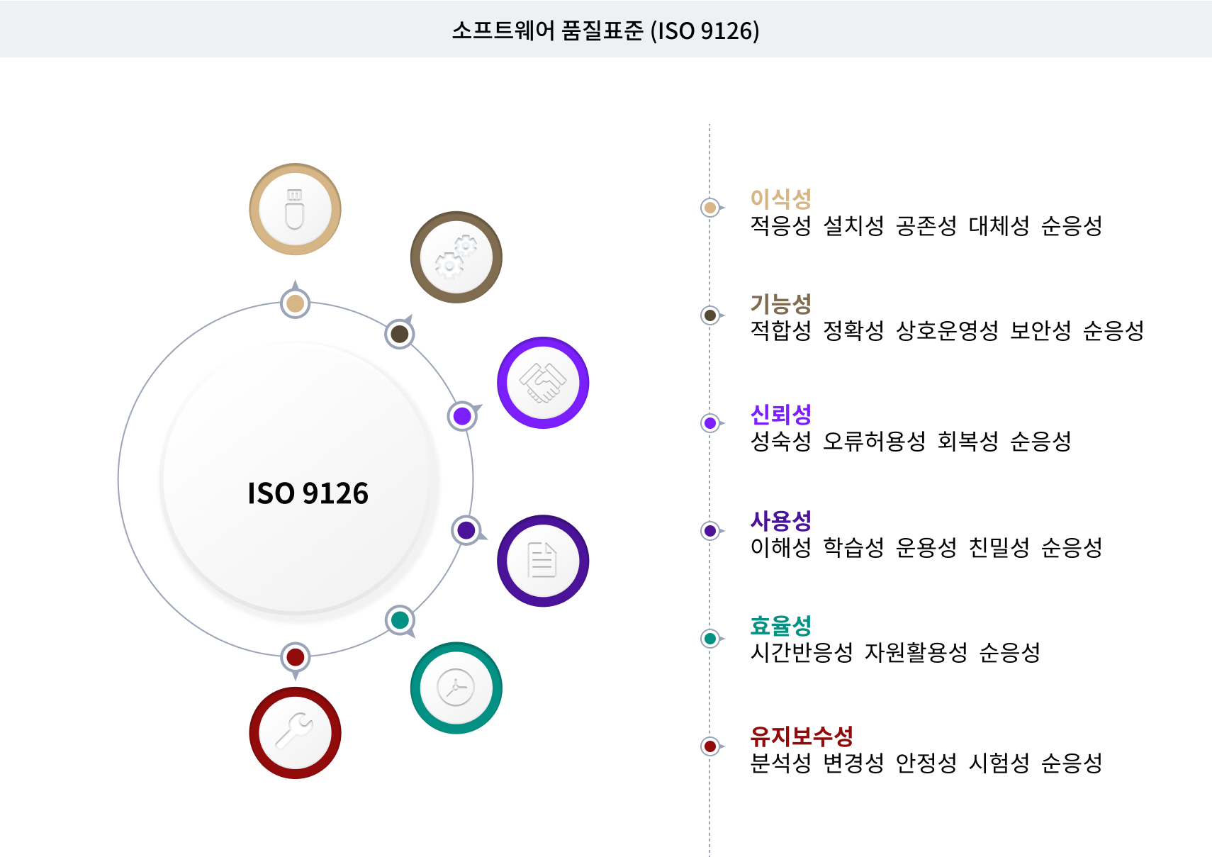
소프트웨어 품질표준
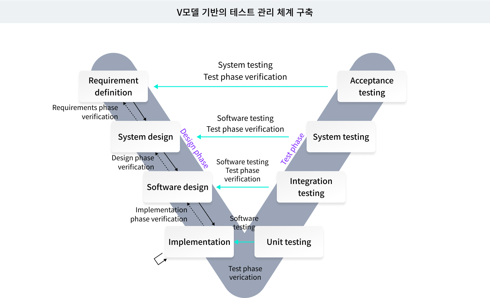
소프트웨어 테스트 모델
소프트웨어 테스트 컨설팅